Training Contents
- Scientific fundamentals of ultrasonic testing
- Probe design, sonic field and device engineering
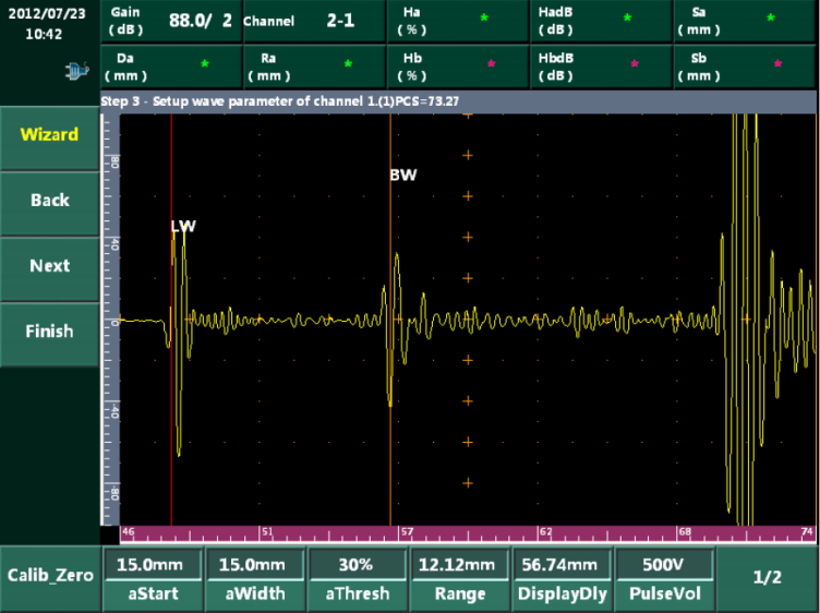
- Device calibration using standardized calibration blocks
- Fundamentals of perpendicular wave incidence
- Ultrasonic testing of rolled products and forgings
- Ultrasonic testing of castings
- Ultrasonic testing of weld seams in the pipeline, structural steelwork and tank construction fields
- Ultrasonic testing of tubes and pipes in the pipe mill
- Sound propagation laws
- Distance and sensitivity adjustments
- Checking and monitoring ultrasonic testing equipment
- Influence of materials on ultrasonic testing
- Evaluation of ultrasonic inspection results


- Specimen and flaw analysis: castings
- Inspection techniques and bodies of standards relating to castings
- Specimen and flaw analysis: forgings
- Inspection techniques and bodies of standards relating to forgings
- Specimen and flaw analysis: rolled products
- Inspection techniques and bodies of standards relating to rolled products
- Specimen and flaw analysis: fusion welds
- Inspection techniques and bodies of standards relating to fusion welds
- Pipe and tube manufacture, faults and inspection techniques in the pipe mill
- Techniques and bodies of standards relating to the ultrasonic inspection of tubes and pipes
- UT of dissimilar welds
- NDT Lab Reporting
About the course
This training course communicates basic know-how and skills with regard to the ultrasonic inspection of weld seams, castings and wrought products. Basic inspection techniques such as the use of perpendicular and oblique wave incidence and contact and immersion techniques are explained and practiced. The calibration of ultrasonic systems by means of calibration blocks forms the basis of the localization and description of reflectors. The training course communicates advanced know-how and skills with regard to ultrasonic inspection. The candidate’s basic knowledge is reinforced, the DAC and DGS method introduced, the parameters impacting on the test results or the specimen’s susceptibility to testing is presented, and know-how relating to the industrial sectors and bodies of standards is communicated.
ABOUT
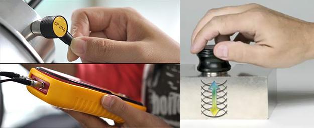
Wall-thickness measurements are often used for maintenance tasks performed on pipelines and in ships. For instance, they serve to detect general erosive corrosion or selective corrosion, cavitation or erosion. Staff carrying out these tasks often have sound knowledge of how to assess the findings thus brought to light without having any further skills or knowledge of ultrasonic testing.
Training Contents
- Scientific fundamentals of ultrasonic testing
- Generation of ultrasound, ultrasonic probes and testing devices
- Device calibration using calibration blocks
- Fundamentals of perpendicular wave incidence
- Defects due to corrosion and erosion
- The use of ultrasound for wall-thickness measurement
- NDT Lab Reporting
ABOUT
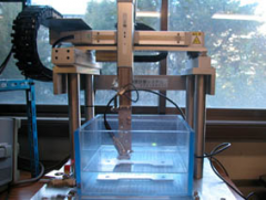
Another way to couple the sound from transducer to a test object is coupling the sound with water. This can be done with squirters where the sound travels through a jet of water or by immersing the transducer and test object in a tank of water. Both techniques are called immersion testing. In immersion testing, the transducer is placed in the water, above the test object, and a beam of sound is projected. The graph of peaks using the immersion method is slightly different. Between the initial pulse and the back wall peaks there will be an additional peak caused by the sound wave going from the water to the test material. This additional peak is called the front wall peak. The ultrasonic tester can be adjusted to ignore the initial pulse peak, so the first peak it will show is the front wall peak. Some energy is lost when the waves hit the test material, so the front wall peak is slightly lower than the peak of the initial pulse.
Training Contents
- Scientific fundamentals of ultrasonic testing
- Generation of ultrasound, ultrasonic probes and testing devices
- Device calibration using calibration blocks
- Fundamentals of perpendicular wave incidence
- Defects due to corrosion and erosion
- The use of ultrasound for wall-thickness measurement
- NDT Lab Reporting
ABOUT
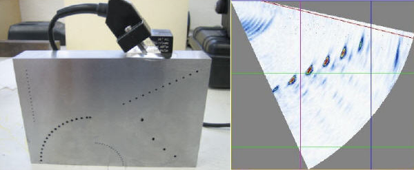
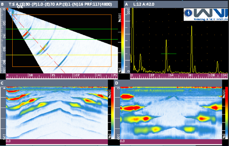
Ultrasonic phased arrays use a multiple element probe whereby the output pulse from each element is time delayed in such a way so as produce constructive interference at a specific angle and a specific depth. These time delays can be incremented over a range of angles to sweep the beam over the desired angular range. For example, 40 to 75 degree beam sweep would be produced by calculating the time delays to produce constructive interference at 40, 41, 42 …75 degs.
This NDT technology is also referred as Swept Beam Ultrasonic testing. The main advantages of phased array in NDE are:
- Ability to sweep a range of angles
- Ability to display the image in real time for the swept angles
- Ability to focus
Training Contents
- Scientific fundamentals
- Probe design, sonic field and device engineering
- Device calibration using standardized calibration blocks
- Inspection techniques
- Specimen and flaw analysis
- NDT Lab Reporting
ABOUT
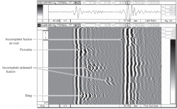
Time of Flight Diffraction (TOFD) method of Ultrasonic inspection is a very sensitive and accurate method for non destructive testing of welds for defects. TOFD originated from tip diffraction techniques. Measuring the amplitude of reflected signal is a relatively unreliable method of sizing defects because the amplitude strongly depends on the orientation of the crack. Instead of amplitude, TOFD uses the time of flight of an ultrasonic pulse to determine the position of a reflector.
In a TOFD system, a pair of probes sits on opposite sides of a weld. One of the probes emits an ultrasonic pulse that is picked up by the probe on the other side. In undamaged pipe, the signals picked up by the receiver probe are from two waves: one that travels along the surface and one that reflects off the far wall. When a crack is present, there is a diffraction of the ultrasonic wave from the tip(s) of the crack. Using the measured time of flight of the pulse, the depth of a crack tip can be calculated automatically by simple trigonometry. This method is even more reliable than Radiographic testing of a weld.
Training Contents
- Scientific fundamentals of TOFD ultrasonic testing
- Probe design, sonic field and device engineering
- Device calibration using standardized calibration blocks
- Inspection techniques
- Specimen and flaw analysis
- NDT Lab Reporting